Employed Modules
The following VME modules are employed in the standard DRAGON hardware configuration:
- IO32 General purpose control board
- CAEN V812 Constant fraction discriminator (16 channel)
- CAEN V792 Charge-sensing ADC (32 channel)
- CAEN V785 Peak-sensing ADC (32 channel)
- CAEN V1190 Multi-hit TDC (64 channel)
The “head” or gamma-ray setup consists of 1x IO32, 2x V812, 1x V792, and 1x V1190, while the “tail” or heavy-ion side has 1x IO32, 2x V785, and 1x V1190. In addition, a wide variety of NIM modules are employed for purposes such as signal amplification, fan-in/fan-out, level conversion, signal delay, and so on.
CAEN Modules
For more information about the various CAEN modules used at DRAGON, the reader is referred to the official manuals. For convenience, a .pdf copy of each of these is available on ‘draco’ in the ~/Documents/Manuals directory.
IO32 Module
The IO32 is a home-brewed VME module from TRIUMF. A manual/documentation page for the device is maintained at http://www.triumf.info/wiki/DAQwiki/index.php/VME-NIMIO32. In this section, we’ll go a bit into some of the specific functions used with DRAGON, as well as the various input and output signals pertaining to the device.
First a brief overview of the capabilities. The IO32 contains an internal Altera Cyclone FPGA, allowing arbitrary logic functions to be programmed into the device. It also contains a 20 MHz (nominal) quartz oscillator for clocking functions. Each device has up to 32 available input channels and 16 output channels. The 32 input channels are broken up into 16 ECL inputs, fed by a ribbon cable on the side of the device, and 16 NIM inputs, while the outputs are all NIM. The NIM connectors are located on the front of the device, with the outputs on top [left] and the inputs on bottom [right]. The 16 input or channels are organized in the following pattern:
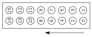
Note that since some of the NIM inputs or outputs are unused, they may not actually be present on a given board. Now that you know what’s available, here’s a list of the utilized input and output channels on the device. To help understand this, it may be useful to read the trigger logic section of the manual first.
ECL Inputs
The ribbon cable feeding the IO32 ECL inputs is fed directly into a NIM to ECL level converter, effectively making it a grouping of 16 NIM inputs. The first eight channels [0, 7] (labeled [1, 8] on the LeCroy NIM->ECL converters)make up the “grand” or “master” trigger for the respective head or tail system. Internally, these signals are sent through a bitmask to disable/enable individual channels, and then enabled ones are ORed to create a single trigger signal. They are also sent through some logic which allows one to determine which of the eight inputs generated the trigger. Some of the ECL inputs are also routed into scaler channels; for more information see the section on scalers.
Presently, the ECL inputs to the tail side are as follows:
| ECL_IN Channel | Input Signal |
|---|---|
| 0 | DSSSD trigger. |
| 1 | Ion chamber trigger. |
| 2 | MCP trigger. |
| 3 | Surface barrier trigger. |
| 4 | NaI trigger. |
| 5 | Ge trigger. |
| 6 | Empty. |
| 7 | Coinc pulser. |
| 8 | MCP 0 scaler. |
| 9 | MCP 1 scaler. |
| 10 | SB0 scaler. |
| 11 | SB1 scaler. |
| 12 | Ge scaler. |
On the head side, the following ECL inputs are used:
| ECL_IN Channel | Input Signal |
|---|---|
| 0 | OR of CFD 0. |
| 1 | OR of CFD 1. |
| 7 | Coinc pulser. |
NIM Inputs
DRAGON makes use of the following NIM input channels:
-
NIM_IN 0 - “Cross System Trigger”: This input accepts a copy of the trigger signal from the other DAQ system it is fed into the timestamp counter, allowing the time difference between triggers (head and tail) to be measured.
Note: currently, this signal is disabled by the TSC4 routing (settable via the ODB); see the relevant section of the operation guide for more information. -
NIM_IN 1 - “System Trigger: This input accepts the trigger signal from its own system, and is routed into the timestamp counter. This is the actual signal which is used for coincidence matching using timestamp values.
-
NIM_IN 2 - “Trigger 1”: This signal is ORed with NIM_IN 3 to generate the final system trigger, as well as other pulses that need to happen for every event (ADC gate, TDC trigger, busy pulse, etc.).
-
NIM_IN 3 - “Trigger 2”: See above.
-
NIM_IN 4 - “TSC Reset” [tail only]: Receipt of a signal at this channel causes the timestamp counter (TSC) to be reset to zero.
-
NIM_IN 5 - “40 MHz Clock” [tail only]: Signal driving the clocking functions on the tail side. See NIM_OUT 3 for more information.
NIM Outputs
DRAGON makes use of the following NIM output channels:
-
NIM_OUT 0 - “TS Reset” [head only]: This pulse is generated every time a new run is started, at virtually the exact time that the head’s timestamp counter is reset to zero. The pulse is fed into the tail side, where it is used to reset the tail’s timestamp, ensuring clock synchronization at the nanosecond level.
-
NIM_OUT 1 - “DAQ Busy”: This is a logic pulse that reads “true” whenever the system is busy processing an event. In normal running, it is not used as the IO32 can internally veto any potential triggers received while busy. However, it can prove quite useful for diagnostics.
-
NIM_OUT 2 - “Pulser”: Square wave pulser output. The frequency can be adjusted as explained in the IO32 operation section.
-
NIM_OUT 3 - “40 MHz Clock” [head only]: The output is a 40 MHz (nominal) square wave, whose precise frequency is exactly double that of the internal clock. This is fed into the tail system and used as an external clock input, ensuring that both systems run on exactly the same frequency.
-
NIM_OUT 4 - “IO32 Trigger”: This signal is generated whenever the OR of NIM_IN 2 NIM_IN 3 receives a pulse. It’s main purpose is to be sent into NIM_IN 1 for timestamp recording. -
NIM_OUT 5 - “TDC Trigger”: This is the trigger pulse sent into the V1190 TDC. It is generated whenever there is an “IO32 trigger”, and can be arbitrarily delayed with respect to the initial trigger pulse. For more information, see the IO32 operation section of the manual.
-
NIM_OUT 6 - “ADC Gate”: This is the gate pulse sent into the V792 or V782 ADC(s). As with the TDC trigger, it is generated every time there is an “IO32 trigger”, and it’s width is programmable (again, see the IO32 operation section of the manual for more information).
- NIM_OUT 7 - “Grand OR”: This signal is the OR of unmasked ECL inputs 0 - 7. It is routed back into the IO32 via either NIM input 2 or 3.
Scalers
The IO32 allows any 16 of its inputs (NIM or ECL) to be routed into scalers. This section deals with how to set which inputs are routed into scaler channels. For a more general discussion of IO32 scaler capabilities, see the following: http://www.triumf.info/wiki/DAQwiki/index.php/VME-NIMIO32#Scalers.
IO32 scaler inputs are set in groups of four channels, starting with NIM_IN 0. So, the first available group is NIM_IN 0..3, the second is NIM_IN 4..7, the 5th is ECL_IN 0..3, etc. For DRAGON, the scaler routing is set by the /Equipment/xxxVME/Settings/IO32/Scaler_route ODB key, where xxx is either Head or Tail. This ODB key is an array of four integers, where each array entry determines scaler inputs as follows:
| Index | Scaler Channels |
|---|---|
| 0 | 0..3 |
| 1 | 4..7 |
| 2 | 8..11 |
| 3 | 12..15 |
The values entered into the array determine input channels according to the following scheme:
| Value | Scaler Inputs |
|---|---|
| 0 | NIM_IN 0..3 |
| 1 | NIM_IN 4..7 |
| 2 | NIM_IN 8..11 |
| 3 | NIM_IN 12..15 |
| 4 | ECL_IN 0..3 |
| 5 | ECL_IN 4..7 |
| 6 | ECL_IN 8..11 |
| 7 | ECL_IN 12..15 |
So for example, setting Scaler_route[2] = 5 means that scaler channels 8, 9, 10, and 11 will count pulses sent into ECL_IN 4, 5, 6, and 7, respectively.
The default scaler settings are as follows:
| Index | Value |
|---|---|
| 0 | 4 |
| 1 | 5 |
| 2 | 6 |
| 3 | 0 |
This routes each of the signals going into the “grand OR” trigger (ECL inputs 0..7) into the corresponding scaler channel (ECL_IN[0] → scaler channel 0, etc.), with the next four ECL inputs (8..11) also going into scalers with the same 1:1 ECL_IN:scaler channel correspondence. Finally, the last four scaler channels (12..15) correspond to NIM inputs 0..3, which correspond to the following signals:
| NIM_IN | Signal |
|---|---|
| 0 | “Crossover” triggers acquired |
| 1 | Triggers acquired |
| 2 | Triggers presented 0 |
| 3 | Triggers presented 1 |
Note that the total triggers presented is the sum of triggers presented 0 and 1 since both of these NIM channels are ORed to make the final trigger. However, in the standard configuration, only one of the inputs is actually connected.
For a listing of the ECL scalers, see the ECL inputs section.
Finally, nonte that there is actually a 17th scaler channel (labeled ch. 16 since we start from zero). This scaler channel contains the clock signal used to calculate instantaneous counting rates for the other 16 scalers.
EPICS Scalers
The table below documents which signals are plugged into the various EPICS
scalers. These can be striptooled by connecting to DRA:VSC1:SCALER.Sn, where
n is the channel number (1–16).
| Channel Number | Signal |
|---|---|
| 1 | Clock?? |
| 2 | Head triggers presented |
| 3 | Head triggers acquired |
| 4 | ED1 X-ray counts |
| 5 | ED2 X-ray counts |
| 6 | Beta monitor |
| 7 | Empty |
| 8 | Tail triggers presented |
| 9 | Tail triggers acquired |
| 10 | DSSSD front trigger |
| 11 | Ion chamber trigger |
| 12 | MCP trigger |
| 13 | SB trigger |
| 14 | NaI trigger |
| 15 | Ge trigger |
| 16 | Empty |
ADC Inputs
In the standard wiring, the adc channels are mapped as follows:
Head
| Channel | Signal |
|---|---|
| 0 | BGO 0 anode |
| 1 | BGO 1 anode |
| … | … |
| 29 | BGO 29 anode |
Tail
ADC0
| Channel | Signal |
|---|---|
| 0 | DSSSD front strip 0 |
| 1 | DSSSD front strip 1 |
| … | … |
| 15 | DSSSD front strip 15 |
| 16 | DSSSD back strip 0 |
| 17 | DSSSD back strip 1 |
| … | … |
| 31 | DSSSD back strip 15 |
ADC1
| Channel | Signal |
|---|---|
| 0-15 | [empty] |
| 16 | Surface barrier 0 |
| 17 | Surface barrier 1 |
| 18 | MCP 0, anode 0 |
| 19 | MCP 0, anode 1 |
| 20 | MCP 0, anode 2 |
| 21 | MCP 1, anode 3 |
| 22 | MCP TAC |
| 23 | HPGe |
| 24 | IC TAC |
| 25 | IC anode 0 |
| 26 | IC anode 1 |
| 27 | IC anode 2 |
| 28 | IC anode 3 |
| 29 | IC anode 4 |
| 30 | NaI 0 |
| 31 | NaI 1 |
Threshold[0..15] = [empty], Threshold[16] = SB0, Threshold[17] = SB1,…,Threshold[31] = NaI 1, Threshold[32] = DSSSD front strip 0,…etc.TDC Inputs
In the standard wiring, the tdc channels are mapped as follows:
Head
| Channel | Signal |
|---|---|
| 0 | BGO 0 [from CFD] |
| 1 | BGO 1 [from CFD] |
| … | … |
| 29 | BGO 29 [from CFD] |
| 30 | [empty] |
| 31 | [empty] |
| 32 | RF |
| 33 | head trigger (ECL 0-7 OR) |
| 34 | tail “crossover” trigger |
| 35-63 | [empty] |
Tail
| Channel | Signal |
|---|---|
| 0 | IC anode 0 |
| 1 | IC anode 1 |
| 2 | IC anode 2 |
| 3 | IC anode 3 |
| 4 | DSSSD front strips |
| 5 | DSSSD back strips |
| 6 | MCP 0 |
| 7 | MCP 1 |
| 8 | RF |
| 9 | tail trigger (ECL 0-7 OR) |
| 10 | head “crossover” trigger |
| 16-63 | [empty] |
Special Notes
-
The V792 module that we use in the head setup apparently has an issue with the front panel ECL connections; in particular, it appears to generate a “reset” signal on its own for some small fraction of events. This causes events to be lost as the data buffer is cleared by the reset signal. This problem has been communicated to CAEN, but their engineers appear to be stumped. In the meantime, we can make the problem go away by manually driving the ECL reset input to logic level 0. This is accomplished by connecting 2-pin cable from the ECL output of a Phillips Gate & Delay generator into the ECL reset input on the V792. As long as no output is generated at the Phillips module, the reset input stays at logic level 0 and there are no inadvertent resets.
-
One important feature of both the V792/V785 ADC and the V1190 TDC is that their respective “gate” or “trigger” inputs consist of two I/O NIM channels linked together. This allows one to “daisy chain” multiple modules together, or to view a gate (trigger) signal on the scope while still providing it to the device. However, the end of the gate (trigger) chain must be terminated by 50 ohms. If not, the device could randomly fail to receive gate (trigger) signals when expected, leading to errors. One common cause of problems is plugging the final stage in the chain into an oscilliscope channel which is set to 1 MΩ termination. This will cause problems, so if you plug the signal into a scope, be sure it is set to 50 Ω termination.