Overview
The following image gives a overview of the trigger logic for two arbitrary detector signals. Note that this is a “bare bones” description of the logic, including only the bare minimum required to make the system operate. In reality, various signals will need to be further branched and sent to other places–for example, to EPICS channels or to visual scalers.
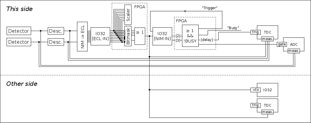
The signals are first split into an “analog” and a “digital” branch, with the analog branches being fed into ADC measurement channels to be either integrated or to have their maximum height recorded. The digital branches are fed into a discriminator unit, to turn them into a logic pulse whose leading edge corresponds in some way on the arrival time of the pulse (the exact correlation depends on whether leading-edge or constant-fraction discriminators are being used).
The discriminator output is split, with one branch being fed into a TDC measurement channel, to record the time of the pulse’s arrival. The other branch is fed into the IO32’s ECL input (channels [0, 7]) via a NIM to ECL converter. Each of these channels (along with all of the other ECL and NIM inputs to the IO32) is routed into a scaler for rate counting. They are also passed through a bitmask, with those channels surviving the mask being ORed to make a “grand” trigger signal.1 This signal is split and routed into a number of places:
- A TDC channel on its own side, to provide a jitter-free timing reference for all measurements.
- A TDC channel on the other side, to allow timing measurements between “head” and “tail” detectors (allowing calculation of the all-important “separator ToF” parameter).
- The IO32 timestamp counter on the other side, to give a cross check for coincidence matching.
- The IO32 NIM input on its own side, to trigger a system readout if the DAQ is not busy.
The portion of the “grand” trigger fed back into the IO32 is ORed with the input of another channel (allowing an optional trigger generation from signals not part of the “grand” trigger). The system then does an internal check that it is not busy, and if it isn’t, then the readout sequence is triggered. In other words, the final “system” trigger is an OR of two IO32 NIM inputs–one of which is the OR of the unmasked ECL inputs [0, 7]–ANDed with the system not being busy.2 Generation of a “system” trigger prompts a number of events, including the eventual reading of data from all VME modules and the generation of an internal busy signal to reject subsequent triggers. Additionally, a number of output pulses are generated:
- A gate signal which is routed into the ADC(s) on the present side. The width of this signal is adjustable, allowing for different gate widths depending on experimental needs.
- A trigger signal sent in to the TDC on the present side. This signal is typically delayed with respect to the “system” trigger, meaning it effectively serves as a “common stop” for the TDC. The length of this delay is adjustable. Note that because the delay is achieved by counting cycles of a 100 MHz clock, it will jitter by 10 ns relative to the “system” trigger pulse arrival.
- A “system trigger” signal which is fed back into an IO32 input. Note that this is the signal which is routed into the IO32 timestamp counter and used for coincidence matching.
- A busy signal that reads “true” for the entire time the system is processing the event. Currently, this signal is unused.
Detector Signals
The previous section assumed generic detectors that were to be measured and used to generate triggers for the DAQ. In reality, of course, these signals come from specific places, as expanded upon here.
Head
On the head or γ-ray side, each of the 30 BGO signals is split, with one branch going to the ADC (including an appropriate delay to put it inside the gate) and the other fed into a constant-fraction discriminator (CFD) channel. Due to the number of signals, two CFDs are employed, with each able to accommodate up to 16 signals. Each channel of the CFD has an individual output that is fed into a TDC measurement channel. Additionally, each CFD provides an OR output that fires any time one of its channels receives a signal. These two OR outputs are what is fed into the IO32 ECL input to generate the “grand” trigger for the head side.
In addition to the CFDs, the accelerator RF pulse is also fed into one of the TDC measurement channels, to provide a time reference that correlates with the generation of a beam particle.
Tail
The tail or heavy-ion detector signals are a bit more haphazard than the head ones. The signals originate from a variety of different detector types and have different needs regarding amplification and discrimination. Additionally, the various detectors serve different purposes. Some are recoil detectors aiming to detect the recoils produced in capture reactions, while others are for diagnostic purposes such as determining the incoming beam rate via elastic scattering. In any case, the signal from any given detector eventually ends up producing an analog pulse to be sent into an ADC measurement channel and a digital pulse to be sent to a TDC measurement channel and to be used in the trigger logic. The various logic pulses are routed into the IO32 ECL inputs [0, 7] making them part of the tail “grand” trigger, which is essentially an OR of all heavy-ion detectors.
In some cases, the signals from diagnostic detectors may be coming at too high of a rate to be fed directly into the trigger. When this is so, the signal is split, with one branch going into a down-scaler before being input into ECL inputs [0, 7]. The other branch is fed directly into one of the other ECL inputs, routing it into a scaler but avoiding making it part of the trigger. Note that there is a hope of future upgrades to the IO32 firmware that would allow the splitting and trigger down-scaling to be performed in the FPGA, eliminating the need to split and downscale the signal externally.
Finally, as with the head side, the RF pulse is also routed into a TDC channel to provide a beam-based timing reference.
Timestamp Counter
Although not part of the trigger logic per se, the IO32’s timestamp counter (TSC) is vital for identification of coincidence or singles events. This identification used to be done completely using NIM and CAMAC hardware signals, requiring a very complicated system of trigger logic relying on multiple signals sent across the room for each crate to report to the other what its status is. Essentially, this is now all replaced by identification of coincidences based on timestamps, greatly simplifying the hardware trigger logic.
Clocks
The recording of timestamps relies on accurate clocking as what re refer to as a timestamp is really just a count of the number of clock cycles that have passed since a certain reference time. In the IO32s, clocking is performed by referencing a quartz oscillator that has a nominal frequency of 20 MHz. Thus each clock cycle corresponds to a period of 50 ns–the result of taking the inverse of 20 MHz.
In reality the clocks are not perfect; the crystals do not vibrate with a frequency of exactly 20 MHz, and their frequency varies by some amount over time, the exact amount depending on the crystal specifications. The crystals employed in the IO32 are rated to 50 parts per million, which means that their period can vary by around 0.5 ns per clock cycle. This may not seem like much, but over the course of only a few minutes an clock can easily become “off” by a few microseconds relative to an initial reference:
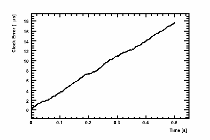
The above can be mitigated somewhat by applying an correction to the initial frequency difference between clocks; however, drifts on the order of a few microseconds are still observed after only a minute or so. Given that sub-microsecond precision is required for DRAGON coincidence matching, it is necessary to calculate both the head and the tail timestamp values based on the same clock reference. For this purpose, the IO32 has the option to accept an external clock input as a driver, instead of using its own internal quartz clock. The procedure, then, is to send a duplicate of the head IO32 clock signal into the tail IO32 external clock input.
TSC4 Register
Timestamp values in the IO32 are stored in a section of the device referred to as the “TSC4 register”. Signals from up to four of the NIM or ECL inputs can be routed into the TSC as inputs. The TSC register acts as a FIFO (first-in, first-out) container; that is, when it is time to read this particular section of memory, the data will be stored in order of arrival.
As mentioned, the TSC4 consists of a series of data corresponding to pulses arriving at the chosen four TSC input channels. Each datum is a 32-bit word, with the upper two bits denoting which input channel is belongs to and the lower 30 bits indicating the clock cycle at which the pulse arrived. Note that the counter is effectively only 30-bits, meaning that it will roll over after 1,073,741,823 [0x3fffffff] clock cycles, or 53.69 seconds. The frontend code is equipped to handle this rollover and stores the data as a 64-bit word, extending the rollover time to over 29 thousand years, well beyond the length of a typical DRAGON run.
Zeroing
It is desirable to reset the timestamp counter at the beginning of every run; that way, the TSC is simply a measure of the number of seconds that have passed since the run started. The IO32 allows the TSC to be reset in one of two ways, either in software by writing the appropriate bits to a firmware register, or by sending a logic pulse into the appropriate input channel (“external tsc reset”). Because the two TSCs need to be synchronized to a very high level of precision, it is not possible to reset them both using software, as this relies on the transit time of network signals which can vary on the order of microseconds. Instead, a set scheme is used to reset the clocks at nearly the same time. First the head clock is reset using the software option; at the same time, the head IO32 sends a logic pulse to the “external tsc reset” input of the tail IO32. This ensures that the reset time of the two TSCs will differ only by the transit time of the reset signal sent to the tail IO32. As the transit time is on the order of tens of nanoseconds (assuming a minimal length of cable to send the signal across the room), it is negligible with respect to coincidence matching, which deals with times on the order of microseconds. However, if desired, the synchronization could be improved by measuring the signal transit time and accounting for it in software.
The synchronization scheme requires a very precise sequence of actions to be carried out by the frontend codes of both the head and tail DAQ. In particular, the tail system must always complete its initialization routines before the head starts in on its own. To accomplish this, we set the appropriate priority levels in the MIDAS transition handler routines, ensuring that everything is done in the right order.